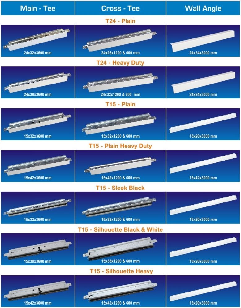

T-Grid-Suspension Details
| System Specifications | |
|---|---|
| Ceiling Suspension | Cepro T-Grid Ceiling System |
| Body of the Grid | Hot dip galvanized steel with a zinc coating |
| Exposed Flange of the Grid | 24mm or 15mm wide made by the process of hot dip galvanized steel capping |
| White Finish | Factory-coated with a polyester coating thickness of 25 microns |
| Main Runner Specifications | |
|---|---|
| Main Runner | 38/32m high with rectangular bulb |
| Main Runner Length | 3600mm or 3000mm |
| Equipment | Equipped with a effective self-locking (plug in) device which can be joined firmly to for a continuous straight line |
| Hanger Holes | Round and punched on the web of the main runner at interval of 150mm (6") |
| Cross-T Slots | Accurately punched on the web at 150mm (6") o.c |
| Suspension | Suspended at every 1200 mm (centre to centre) |
| Cross-T Specification |  |
|
|---|---|---|
| Wall Angle Specification | 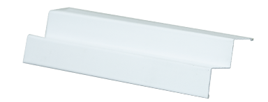 |
|
| Hanger Wires |  |
|
Installation Guide:
-
Site Conditions:
- Modular ceilings are among the last equipments to be installed at the site because it is a pre-finished product. Therefore, the building is expected to be in suitable condition, with regard to humidity, cleanliness etc., before installation of modular ceiling begins.
- The installation site is expected to be fully enclosed and all wet work should be completed beforehand and dried.
- All installations (ducting, insulation etc.) must be installed before laying the T-Grid system and Cepro ceiling tiles.
-
Levelling:
- Sufficient information shall be clearly indicated on the drawings to enable the ceiling module and setting out points in each ceiling area applicable to all relevant trades to be established early.
- The ceiling height in each area shall be marked in relation to the elevation bench marks and then transferred by means of water level.
-
Top fixings:
- The suitability of the site will be verified before installing the suspension system.
- The top fixings are best installed with the T-grid system as this will maintain the dimensional integrity.
-
Hangers:
- When the hangers cannot be installed at the recommended dimensions, an appropriate suitable subgrid will be installed based on the site dimensions.
- Hangers to be installed will be vertical or nearly vertical and shall not press against insulation covering ducts or pipes. If hangers have to be fixed diagonally to avoid obstructions the horizontal force shall be offset by bracing.
-
Main Runners:
- Levelling of the main runners shall be done with the supporting hangers. This will prevent downward movement when tiles are loaded.
- To ensure proper levelling, any bending of the material will never be undertaken.
- The main runners shall be suspended by means of a GI wire of 2/2.5mm diameter or 4mm rod at every 1.2m and not more than 150mm from the spliced joints.
- The last hanger at the end of each main runner should not be more than 450mm from the adjacent wall.
-
Hanger Wires:
- The loops shall be sharply bent and tightly wrapped to prevent vertical movement of the runner within the loop, wherever it passes through the main runner. The wire shall be wrapped around itself a minimum of the full turns within a 3 inches length.
-
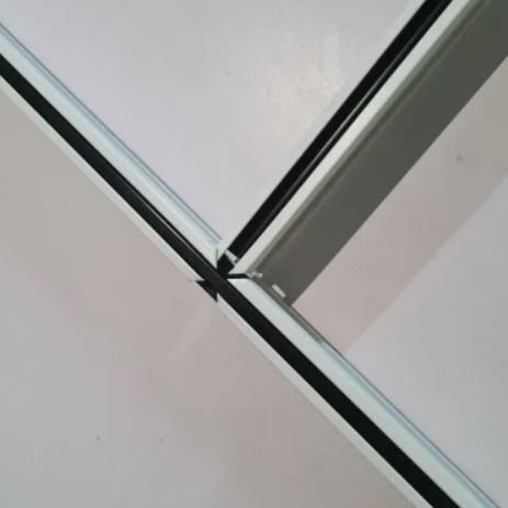
Cross-T’s:
- Cross-T’s are installed on the main runners in a right angle.
- The 1200mm long Cepro Cross-T is attached to two main T section.
- Then the 600mm long Cepro Cross-T is filled between 2 sections of 1200 cross-T’s.
-
Wall Angle:
- The wall angles are neatly joined around the corners. The straight line wall angles shall be completely in line.
- The wall angles shall be firmly screwed to the wall at every 300mm.